Ground Control System
Installation
The SteelEagle GCS is comprised of two components: a frontend browser application written in React (JSX) and a FastAPI backend (python) that returns data to the frontend by interfacing with the other backend components.
In the SteelEagle repo, the frontend code resides at: ~/steeleagle/gcs/react/prime.
The FastAPI backend resides at: ~/steeleagle/gcs/react/backend.
In order to quickly build the GCS, an installation shell script exists. This script will install nvm (used to manage versions of npm), npm (package manager), and build the frontend React application into a set of static files. It will also install uv, and use it to install the dependencies required by the FastAPI backend.
cd ~/steeleagle/gcs/react
sh -x install.sh
The Orchestrator CLI can install and build the GCS for you instead:
steele gcs install
Configuration
There are two configuration files related to the GCS. These configuration files will be generated by the backend setup wizard during initial setup, but can be modified as necessary.
~/steeleagle/gcs/react/prime/src/config.js
- Contains the Mapbox token that is required to load map tiles. A free Mapbox account is required to generate the token. The following guide from Mapbox explains how to get started generating an access token
~/steeleagle/gcs/react/backend/config.toml
- This FastAPI file manages two primary sets of configuration: backends and vehicles. The GCS can either get data directly from local vehicles (the [vehicles] stanza) or by talking to a backend server (the [backend] stanza). A sample config.toml is displayed below that defines two different backends and two local vehicles. The GCS can connect to multiple local vehicles simultaneously, but can only be connected to a single backend at runtime. Which backend to use from the config.toml can be controlled by passing the BACKEND environment variable when launching the GCS.
- For local vehicles, a [vehicle.name] stanza needs to be created that defines the local socket endpoints for that vehicle.
- For backends, a [backend.name] stanza needs to be created that defines where the various backend components can be found (swarm controller, redis db, etc).
[cors]
origins = [
    "*"
]


[backend]
[backend.machine1]
swarm-controller = "machine1.address:5004"
redis_host = "machine1.address"
redis_port = 6379
redis_username = "steeleagle"
redis_password = "<password here>"
webserver = "http://machine1.address:8080"

[backend.machine2]
swarm-controller = "some.other.address:5004"
redis_host = "some.other.address"
redis_port = 6379
redis_username = "steeleagle"
redis_password = "<password here>"
webserver = "http://some.other.address:8080"

[vehicle]
[vehicle.test1]
address = 'unix:///tmp/test1-kernel.sock'
tel_endpoint = 'ipc:///tmp/test1-driver_telem.sock'
img_endpoint = 'ipc:///tmp/test1-imagery.sock'
res_endpoint = 'ipc:///tmp/test1-results.sock'

[vehicle.test2]
address = 'unix:///tmp/test2-kernel.sock'
tel_endpoint = 'ipc:///tmp/test2-driver_telem.sock'
img_endpoint = 'ipc:///tmp/test2-imagery.sock'
res_endpoint = 'ipc:///tmp/test2-results.sock'
cd ~/steeleagle/gcs/react/backend/
BACKEND=machine2 uv run main.py
Usage
The GCS can be launched by using uv:
cd ~/steeleagle/gcs/react/backend/
uv run main.py
This will launch using the default host (127.0.0.1) and port (8002). The host and port can be overridden by using the --host and --port command line parameters respectively. Once launched, the GCS can be reached in the browser at the host/port specified.
The Orchestrator CLI can manage the GCS process instead of running it directly:
steele gcs start
steele gcs logs -f
steele gcs stop
GCS Anatomy
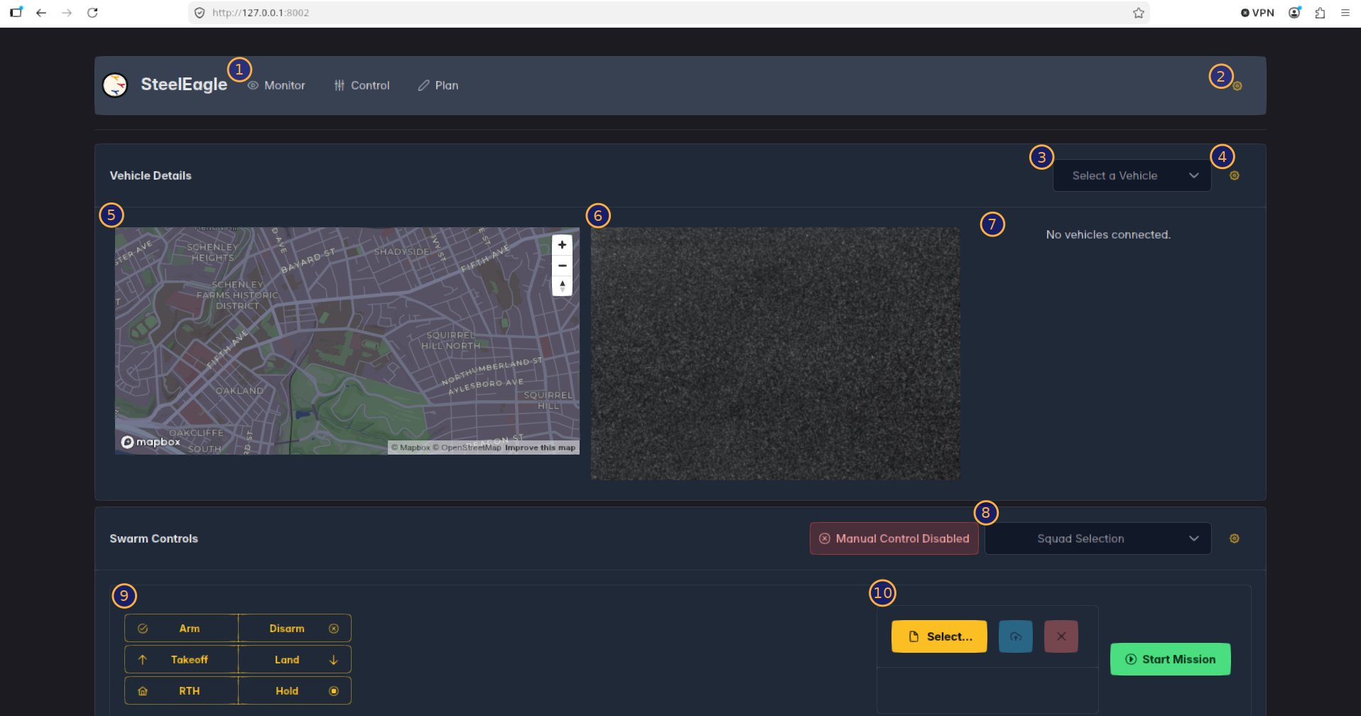
By default, the control page is shown. Below is an explanation of each numbered part of the image.
- Page Selection - Navigate between monitor, control, and plan pages.
- The monitor page displays a large map which tracks the position of all vehicles and detected objects. It also lists the status cards for all connected vehicles.
- The control page allows the user to view a particular vehicle. It also allows both manual and autonomous control of a squadron of vehicles.
- The plan page is a visual mission builder that lets you draw waypoint areas and design a finite state machine mission without hand-writing DSL. See the Plan Page section below.
-
Global Settings Panel - This settings panel allows toggling between two modes: Swarm Controller where it talks to a backend server (this is the default), and Local Vehicles where it will communicate directly with any locally running vehicles.
-
Vehicle Details Selector - This dropdown controls which vehicle is currently being displayed. All connected vehicles will be listed and switching the selection will update the image stream (#6) and the vehicle status (#7).
This is distinct from the Squad Selection dropdown (#8). Changing the Vehicle Details selection will not change which vehicles (if any), are sent control messages. An error message will be generated in a toast popup if control messages are attempted to be sent when no vehicles have been selected.
- Control Settings Panel - The control settings panel displays a number of knobs and buttons that affect the behavior of the GCS. The image below shows these settings; explanations of each follow.
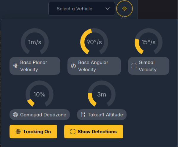
- Base Planar Velocity - The maximum velocity at which the vehicle moves in the planar dimensions (roll, pitch, elevation).
- Base Angular Velocity - The maximum velocity at which the vehicle rotates (yaw).
- Gimbal Velocity - The rate at which the gimbal pitches.
- Takeoff Altitude -The altitude to elevate to upon takeoff.
- Gamepad Deadzone - The percentage of joystick axis inputs are ignored before movement. Useful for gamepads that have some stick drift.
- Tracking Button - Whether or not to have the map snap to the currently selected vehicle so that it is always centered.
- Show Detections - Whether or not to show bounding boxes for detected objects overlaid on the image stream.
-
Map View - The map will display the location of all vehicles, but will snap to the currently selected vehicle when the value of the selector (#3) changes. If tracking is enabled (the default), the map will continuously snap to keep the vehicle centered. The zoom depth can still be changed whether or not tracking is enabled (by using the mouse wheel when focused on the map). Clicking and dragging the left mouse button on the map will pan (only works when tracking is disabled, otherwise it will just snap back to center). Clicking and dragging the right mouse button will pitch and rotate the map.
-
Image Stream - The image stream from the currently selected vehicle. If show detections are enabled (the default), bounding boxes will be overlaid onto the image stream when detections are made.
-
Vehicle Status - The vehicle status card will be displayed for the currently selected vehicle. It contains information such as the current battery level, number of satellites, compass heading, and currently velocities.
-
Squad Selection - This multi-select dropdown allows for one or more vehicles to be selected for control. Only the vehicles selected here can be controlled manually or autonomously (by uploading and starting missions; see #10). To the left of this dropdown is also the Manual Control indicator, which changes depending on whether or not manual control is currently possible.
-
Manual Control Buttons - These buttons issue a number of manual commands to the selected vehicles.
- Arm/Disarm
- Takeoff/Land
- RTH (return to home)/Hold(stop mission and hover)
- Autonomous Control Buttons - These buttons allow a user to select a mission (comprised of both a .kml and .json file), upload it (blue button), and then start the mission (green button). The red X button will remove the currently selected files to allow for a new mission to be uploaded.
Autonomous missions are a two stage process. First, the mission must be uploaded. Then a start mission command must be sent. As long as the mission doesn't change (and the vehicle is not restarted), subsequent calls to start the mission will execute the same mission. If the mission is changed, new files must be selected and uploaded before executing the mission using the mission start button.
Controlling Vehicles Manually
The GCS supports two methods for manual control: keyboard and gamepad. Gamepads can be connected using USB-A/C. When the Manual Control Indicator is disabled, no manual commands will be sent to the vehicles in the squad. Using one of the manual control buttons (#9 above) other than 'Hold' will disable manual control, as will starting an autonomous mission. Manual control can be enabled at any time using the Escape key on the keyboard or the 'Options' button on the gamepad. Below is a list of keyboard and gamepad axis/button mappings.
Currently only PS4/PS5 controllers have been tested. Other gamepads should work in theory, though button mappings may be different.
Keyboard Controls:
- T - Takeoff
- L - Land
- R/F - Pitch Gimbal Up/Down
- W/A/S/D - Planar movement
- I/K - Elevation
- J/L - Rotation
- Escape - Cancel Mission/Enable Manual Control
Gamepad Controls (PS4/PS5):
- Left Stick Up/Down - Elevation
- Left Stick Left/Right - Rotation
- Right Stick Up/Down - Pitch
- Right Stick Left/Right - Roll
- Triangle - Takeoff
- X - Land
- D-Pad Up/Down - Pitch Gimbal
- L1 - Return to Home
- Options Button - Cancel Mission/Enable Manual Control
- Share Button - Disable Manual Control
Running Autonomous Missions
Please see the guide on writing DSL missions for more information on how to craft a mission and compile it. Once a mission is compiled (into a .json file), it can be selected and uploaded to all the vehicles in a squad and executed. The autonomous missions controls in the bottom right of the Control page allow the user to select a set of waypoints (.kml) and a compiled mission (.json) file. After being selected, the files MUST be uploaded to the vehicles participating in the mission, by hitting the blue button with the up arrow. Once the mission files have been uploaded, the mission can be started at any time by pressing the green 'Start Mission' button.
Once a mission has started, it will run to completion unless it is canceled. Canceling a mission can be achieved by enabling manual control on either the keyboard (Escape key) or gamepad (Options button), or by hitting the 'Hold button in the bottom left corner of the GCS. Depending on the behavior of a vehicle's driver, some other actions may be blocking and also interrupt an autonomous mission, such as RTH and Land, though this is not recommended.
Please keep in mind that due to the nature of the control loop in SteelEagle, there is a fair amount of latency between commands issued at the GCS and their execution on the vehicle. The control plane is separate from the data plane, however real networks still have congestion and variability. Furthermore, when autonomous missions are running, actuation of the vehicle naturally builds momentum and even when a Hold command is received by a vehicle, it can take time to decelerate and come to a complete stop.
Utmost caution should be taken when executing autonomous missions and when unsure, missions should be interrupted using the above mechanisms.
Plan Page
The plan page is a visual editor for building DSL missions without hand-writing the finite state machine (FSM) text. It is split into three tabs: FSM Builder, Map, and DSL Preview.
The plan page talks to the same FastAPI backend as the rest of the GCS (/api/schema, /api/compile, /api/parse_dsl, /api/upload), so it requires the GCS backend from Installation to be running with a working steeleagle_sdk DSL compiler.
FSM Builder
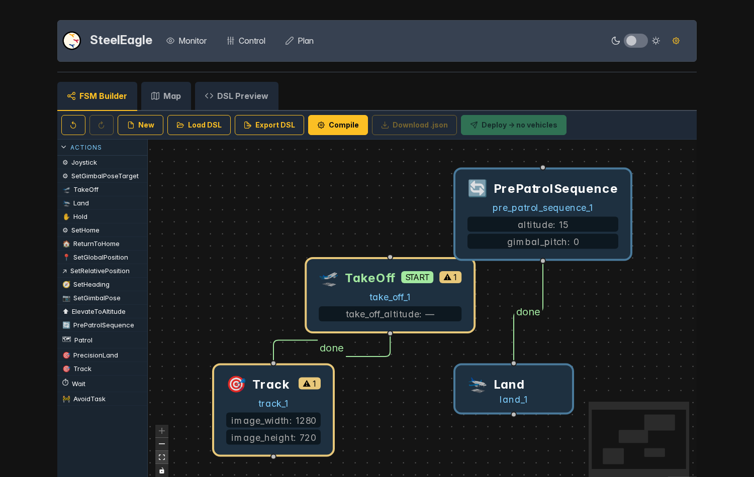
The FSM Builder is made up of three parts:
- Action Palette (left) - A list of every action type the DSL compiler knows about (TakeOff, Patrol, Track, Wait, etc), loaded from
/api/schema. Drag an action from the palette onto the canvas to create a new task node. - Canvas (center) - A React Flow graph where each node is one task instance in the mission. Draw a transition by dragging from one node's handle to another (or back onto itself for a self-loop).
- Toolbar (top) - Undo/Redo, New, Load DSL, Export DSL, Compile, Download .json, and Deploy.
Clicking a node opens a side panel where its instance ID and parameters (as defined by the action's schema) can be edited. Right-clicking a node or transition opens a context menu to set the node as the mission's start state, edit/delete a transition, or delete the node.
When a transition is drawn (including a self-loop), a dialog prompts for the triggering event: the built-in done event (fires on task completion), an existing custom event instance, or a brand new event type/instance defined inline. Clicking an existing transition reopens this same information in a side panel so its event's parameters can be edited or the transition deleted.
As the graph is edited, the canvas is validated on a short debounce and problems are surfaced directly on the offending nodes and in the status bar at the bottom of the canvas:
- Required parameters that are unset
- Duplicate instance IDs
- No start state selected
Ctrl+Z / Ctrl+Shift+Z (or Ctrl+Y) undo and redo the last 50 changes to the graph, including node/edge edits, parameter changes, and deletions.
Toolbar actions:
- New - Clears the canvas after confirmation.
- Load DSL - Parses an existing
.dslfile (via/api/parse_dsl) and rebuilds the graph from it, automatically laying out nodes by distance from the start state. - Export DSL - Downloads the current graph as a
.dsltext file, generated live from the nodes/transitions/events on the canvas. - Compile - Sends the graph to
/api/compile. On success, amission.json(IR the vehicle understands) is produced and the Download .json button is enabled. On failure, the failing node(s) are highlighted and the error is shown in a toast. - Deploy - Uploads the compiled mission (plus any map features from the Map tab, converted to KML) to every vehicle currently selected in the Control page's Squad Selection dropdown, via
/api/upload. A mission must be compiled first, and at least one vehicle must be selected in the squad.
Map
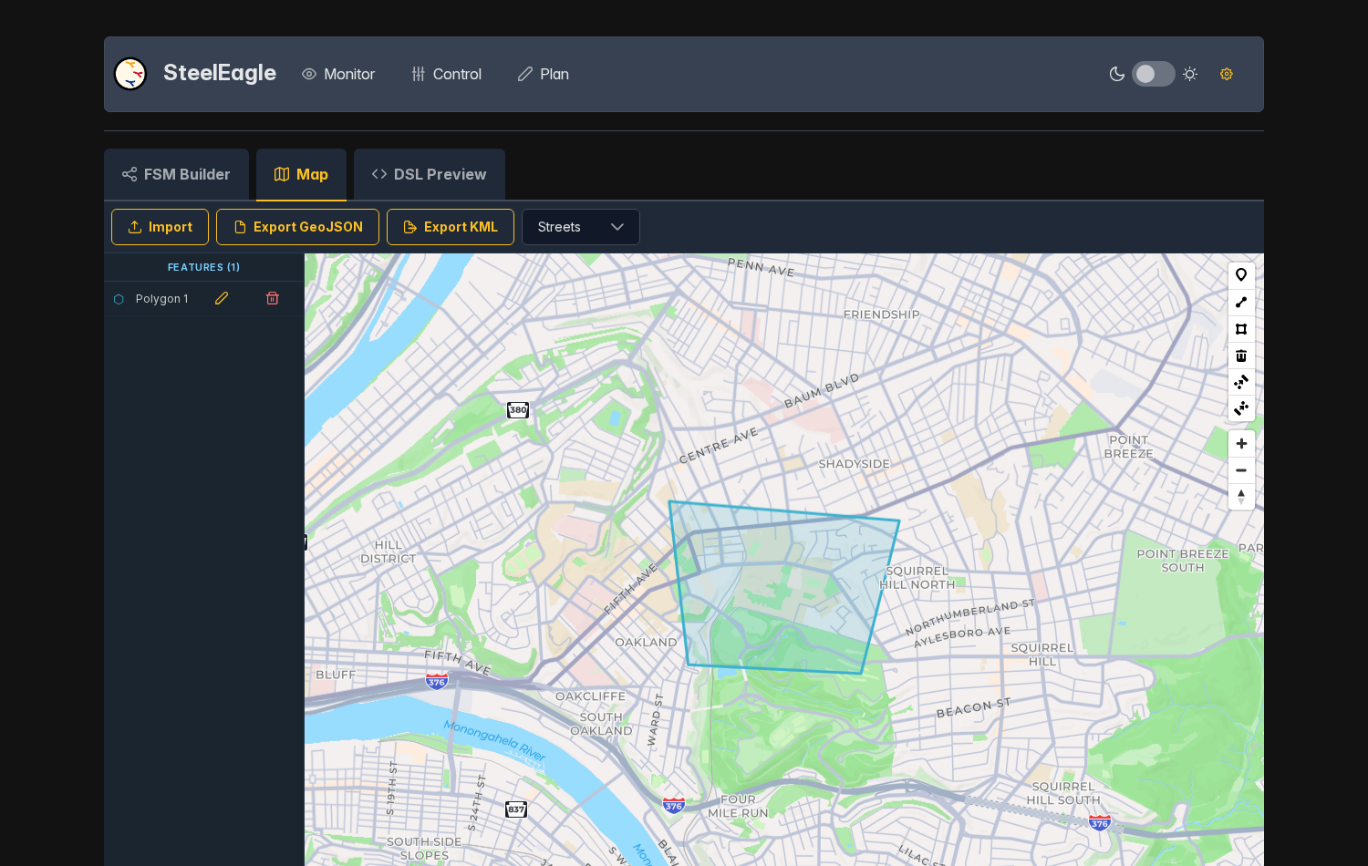
The Map tab is a Mapbox GL drawing surface for defining the named areas/waypoints that patrol, track, and other location-based actions reference:
- Draw polygons, lines, and points directly on the map (satellite or street styles).
- The Features sidebar on the left lists every drawn feature; click one to select and zoom to it, click the pencil icon to rename it, or the trash icon to delete it.
- Named features are exposed to the FSM Builder's parameter panel so location fields can reference them by name instead of raw coordinates.
- Import accepts an existing
.kmlor.geojson/.jsonfile and replaces the current features with it. - Export GeoJSON / Export KML download the current set of drawn features in either format.
DSL Preview
A read-only, live-updating view of the DSL text generated from the current FSM graph. This is the same text produced by Export DSL, useful for reviewing the mission or copying it elsewhere without leaving the plan page. The Export DSL and Download .json (once compiled) buttons are also available here.